How does a gas boiler work, how it works. The device of LPG equipment on a car, components and parts, installation locations, principle of operation Types and generations of LPG
LPG fuel equipment or LPG LPG equipment can be installed on any model of passenger cars equipped with carburetor engines or engines with a fuel injection system and electronic control... If their design allows you to place a cylindrical or toroidal gas cylinder for LPG equipment.
The device of LPG gas equipment on a car, components and parts, installation locations, principle of operation.
The design solutions of the gas cylinder component devices differ in a wide variety depending on the types of engines for which they are intended and on the manufacturers that produce them. The gas equipment of the car is placed in three places: in the engine compartment, the passenger compartment and the luggage compartment. The following are installed in the engine compartment of the car:
- Reducer-evaporator of gas.
- Mixer.
- Electromagnetic gas valve.
- Electromagnetic petrol valve.
Inside the car, they are installed on the dashboard.
- Fuel type switch "Gas - Petrol" with an indication unit for "Gas - Petrol" modes and the amount of fuel in the gas cylinder.
- Fuse.
They are installed in the luggage compartment of the car.
- Gas cylinder with shut-off and safety valves.
- External filling device.
On some models of LPG gas equipment systems, a dosing device is installed, designed to supply a certain amount of gas corresponding to the engine operation mode, except for idling, as well as a tee plug with an adjusting screw or screws.
This steel tank designed for storage of liquefied petroleum gas at temperatures from minus 40 to plus 45 degrees. On a passenger car, it is mounted in the compartment or in the spare wheel well, and on light vehicles - on. The gas cylinder is cylindrical or toroidal. Various volumes and geometric dimensions allow you to choose the best option for placing the balloon in the trunk of a car.
The cylinder is equipped with a ventilation box with a hermetically sealed lid. Under the cover there are filling and supply valves, a scale with an arrow showing the gas level in the bottle, and a filling cup.
In some designs of gas cylinder equipment for filling a gas cylinder it is necessary:
- Open the cover of the ventilation box.
- Close the flow valve.
- Screw the adapter into the filling cup.
- Connect the filling nozzle to the adapter.
- Open the filling valve on the gas bottle.
- Open the valve on the filling nozzle.
After the cylinder is 80-85% filled with gas (a shut-off valve is triggered in the cylinder, and a characteristic click is heard), these operations are performed in the reverse order. Further, if the car is stored outdoors (street storage), the flow valve can be left unclosed.
Installed on a unified flange of a gas cylinder using a gasket that ensures the tightness of the connection. It is a receiving device when filling a cylinder with liquefied petroleum gas and ensures the supply of the latter to the gas pipeline. The block includes an inlet connection and a filling valve with check valve, flow connection and flow valves of the liquid and vapor phases, limiting mechanism for the filling level of the cylinder (multivalve).
The unit is closed with a sealed casing that reliably separates its contents from the interior of the car. Ventilation of the inner space of the casing is carried out through a drain pipe, which is led outside the car body. The cylinder is filled with liquefied gas through the filling valve (3). The gas enters the cylinder, overcoming the forces of the ball (2), which is under the action of the spring.
The cylinder is filled with gas and the float (11) rises. An automatic valve (9) cuts off the flow of gas into the cylinder. The ball (2) blocks the gas return from the cylinder. From the cylinder, gas enters the line through the gas intake tube (10), pressing the ball of the high-speed valve (4) through the flow valve (13).
Under normal operating conditions, the supply and filling valves are in the open position. They are closed when the car is parked for a long time, in the event of a gas leak, as well as in case of malfunctions, maintenance and repair of gas equipment. In case of cylinder heating over 45 degrees, it opens safety valve(1) to lower the gas pressure.
The control arrow (7) on the scale (8) indicates the amount of gas in the bottle. The fuel gauge can be displayed on the fuel type switch in the vehicle interior. The arrow is driven by a magnet mounted in the multivalve (9). Together with the scale, it is protected by a transparent cover (6). The maximum permissible gas volume is pre-set with screws (12).
Designed for refueling a gas cylinder, fastened to the bracket (7) with a nut (8) under the rear bumper passenger car... It is connected to the filling line through the union (10). The gas dispenser nozzle is connected to the body (3) with a rubber gasket (2). Pressurized gas opens valve (6) and fills gas bottle... After the end of refueling, the valve is hermetically closed.
Run the gas line under the floor of the vehicle, away from the exhaust pipes. It is protected from contact with parts by PVC or rubber tubes. The pipelines are fixed to the car body with special brackets using self-tapping screws with an interval of no more than 800 mm. The high-pressure gas pipeline along the entire length from the cylinder to the gas solenoid valve and from it to the reducer-evaporator is made of copper or stainless steel with factory flaring.
If the gas pipeline is made of steel, then its connection to the units of the equipment is carried out using a persistent union nut. Such a connection allows for multiple disassembly, but when tightening, excessive force must be avoided to prevent the bottom of the union nut from breaking off. Wear rings are provided at the ends of the pipeline. The tube is bent to form a ring with a diameter of 50–80 mm, which protects the pipeline from breakage due to vibration.
The tightness of the high-pressure gas pipeline is ensured by a nipple connection of the cone coupling type. This connection includes a pipeline (3), a cone sleeve (1), a thrust nut (2) and a connected part (union). The tightness is achieved by a cone sleeve (1) made of brass. Such a connection allows multiple disassembly with the replacement of the cone coupling with a new one. The sleeve should fit snugly on the tube at a distance of 2-3 mm from its end.
In low-pressure pipelines, rubber hoses made of oil-resistant rubber are used to connect the gas reducer with the mixer. Hose connections on the fittings are secured with screw clamps.
They are installed for the purpose of executing commands that control the supply of gasoline or gas in the power supply systems of vehicles equipped with equipment. In some cases, the valves are structurally combined with filters that purify the fuel entering the system.
Electromagnetic gas valve.
Serves to open the gas supply channel to the reducer and to shut it off when running on gasoline. It is controlled remotely from the passenger compartment by means of the "Gas" - "Petrol" switch. The filters do not require regular maintenance: flushing or replacing is sufficient. In some designs, it should be cleaned every 30,000 kilometers the vehicle is driven. When the ignition is on and the switch is set to the "Gas" position, the valve opens and gas flows through the high pressure pipeline to the reducer-evaporator. With the ignition on, the valve is in the “Closed” position.
Electromagnetic petrol valve.
Serves to open (close) the gasoline supply channel to the carburetor, while the gas supply is shut off. A screw (tap) is provided in the lower part of the valve for mechanical (manual) opening of the valve. In the event of failure of the electronic control unit for gas equipment, this screw should be screwed into the valve (or turn the valve) so that you can continue to move.
The valves in the gas line differ from the valves installed in the gas line, only in the design of the inlet and outlet fittings intended for connecting metal pipes for the gas supply.
Solenoid valve for interrupting or resuming the supply of gas or petrol.
The solenoid valve for interrupting or resuming gas supply or has increased reliability, consumes little current (no more than 0.7 A) and operates at low voltage, the power of the solenoid coil is 4 W. The valve filter does not require regular maintenance, flushing or replacement. The gas filter can be a permanent magnet installed at the inlet to the solenoid gas valve.
The filter gas solenoid valves are controlled by a fuel selector switch. They are designed to shut off the gas supply when the engine is running on gasoline, shut off the gas supply when the ignition is off, and to filter the gas. The solenoid petrol valve cuts off the petrol supply when the engine is running on gas.
The solenoid petrol valve should be installed in such a place that the section of the petrol line between it and the petrol pump is as short as possible. The fact is that when working on gasoline in this area, a constant level of gasoline is maintained, maintained by the gasoline pump. Gasoline can become very hot, causing an unwanted pressure build-up in the hose. And the shorter it is, the safer it is.
For the same reason, it is necessary to pay special attention to the reliable sealing of the connections between the petrol pump and the solenoid petrol valve. The valve is always closed. It serves for remote control of the fuel supply. The valve body has a manual actuator in the form of a handle or a valve. Manual control is used when pumping gasoline with a gasoline pump in the cold season, after a long parking lot and in case of an electromagnet failure.
In this case, the handle or valve is moved to the "Open" position. After pumping gasoline, the handle or valve is set to the "Closed" position - this is their constant position, and the fuel type switch in the cabin is set to the "Petrol" position. If this is not done, the engine will run on both petrol and gas at the same time. In this case, even turning off the remote fuel switch will not help, and this is unacceptable.
Gas reducer-evaporator for LPG equipment on a car.
Designed to convert the liquid phase of the gas into vapor and supply the vapor phase to the mixer. Every 1500–2000 kilometers (on a hot engine), unscrew the plug (screw) located in the lower part of the gearbox and drain the condensate (oily sludge). Reducers-evaporators play an important role in the operation of LPG equipment, therefore, special attention should be paid to them.
Gas reducers installed on cars have the same purpose. They serve to automatically reduce the gas pressure in the power supply system to a predetermined level at a constantly changing gas pressure, depending on its quantity and ambient temperature.
The gas reducer must provide at the outlet the required characteristics of the gas state in a wide temperature range, when changing from one engine operating mode to another. It should automatically shut off the gas supply when the engine is off.
Based on the book "Automotive gas fuel systems".
Vladimir Zolotnitsky.
LPG or LPG equipment are devices that are installed on the car and allow the use of gas as fuel. The use of gas equipment on a car allows you to reduce the cost of gasoline and increase engine life, reduce repairs, and also reduce the amount of harmful emissions. With daily movements in the region of 100 km, the installation of LPG on the car pays off within 3 - 4 months.
WHAT IS HBO
Many motorists have heard about HBO, but do not know the decoding of this abbreviated name. And everything is simple: this is the name of the system of devices that supply gas from the cylinder to the engine, that is, gas equipment. This design is mounted as an auxiliary one, and its presence allows switching from petrol to gas. Consider schematically what is included in this very HBO in the car. To simplify the listing as much as possible: a cylinder, gas pipelines and devices that ensure the correct gas supply. The first important device on the cylinder-motor line is the evaporator.
It is necessary in order to convert liquefied (liquid) propane to a gaseous state using antifreeze from the engine cooling system. Due to the temperature difference, the gas evaporates and, already in this form, enters the gas reducer. What role does the reducer play? The most important: it helps to supply gas in the right amount and controls the pressure. The last section of the pipeline leads to a mixer or a ramp with nozzles (depending on the generation of LPG). The system has a gas filter, because the ingress of mechanical particles into the cylinders of the internal combustion engine is unacceptable.
Manometers are also connected to control the pressure in the cylinder and the reducer. In injection machines, gas equipment is controlled by a separate electronic unit. From it the button "gas / petrol" is displayed in the salon. This means that if LPG is installed, the standard power system also remains, and you can switch to gasoline at any time.
HISTORY OF GAS BALLOON EQUIPMENT
Italy is a pioneer in LPG equipment. More than 50 years ago, small family companies in northern Italy began to master the production of components for converting gasoline cars to gas. Italy to this day is the main supplier of gas equipment for cars and new gas technologies.
Recently, this baton has been actively picked up by countries such as Poland, especially in the field of electronics, Turkey, China and Lithuania. In addition to Italy, which today is the country with the largest distribution of gas equipment for cars, many cars with Euro gas equipment also appeared in Poland, Russia, Ukraine - Milano Ukraine, in South America, India, China and Australia. In many of these countries, car manufacturers directly on the assembly line produce either all-gas or dual-fuel (for example, gasoline and gas) vehicles.
The principle of operation of HBO
Gas equipment for cars operates on various forms of gas: liquefied and gaseous. Most often they use liquefied gas - propane-butane mixture for work. Less commonly, compressed natural gas (methane). There are few methane gas stations, so compressed gas cylinders are not popular. How does the LPG system work? Gas flows from the cylinder through the filter to the reducer. Since it is under pressure in the cylinder (about 16 atm), it moves along the pipe by gravity. Getting into the reducer, the liquefied gas is converted into steam - it evaporates. For this, the reducer reduces its pressure and heats it up. When the engine is running, heat from the engine is used to heat the liquid gas. After the reducer, gas vapors pass through another filter and enter the mixer.
In many systems, LPG enters the mixer through nozzles. Their number corresponds to the number of cylinders - pistons. And their opening is controlled by an electronic control unit. By giving commands to the injectors, the control unit regulates the number of injections and the amount of gas that enters the combustion chamber. The engine is started and the first 20-30 seconds of operation are carried out on gasoline. As soon as the reducer warms up, the gas equipment control system automatically turns on the gas supply and its injection into the combustion system.
In this case, the petrol supply is automatically turned off. The reverse transition to gasoline occurs when the pressure in the gas pipes decreases, that is, when the gas in the cylinder runs out. In addition, the control system has the ability to manually switch between petrol-gas modes. The described principle of operation is a scheme for liquefied propane-butane fuel. For natural gas (methane), a different scheme is used. Since it is a gas, it goes directly to the gas injectors and then to the combustion chamber without a filter and a reducer.
Registration of gas equipment
Gas equipment must be registered with the relevant authorities. This statement is true and severely limits the ability to install HBO with your own hands. The fact is that in order to register gas equipment in the Automobile Inspectorate, you need to present a special certificate and a license for the right to work on the installation of such gas equipment. It turns out that independent interventions in the design of the car are unacceptable.
Among motorists, the question has been raised more than once that a car with an installed but not registered gas supply system cannot undergo MOT. Such cars with HBO refuse to register or deregister from the traffic police. Problems will arise, but only in the absence of appropriate documents for the installed HBO. Documents for LPG can legally also be asked for at a gas station, although in practice this does not arise.
Difficulties are associated with the fact that the installation of any systems, and especially from the 4th generation and above, will require a significant re-equipment of the car. For HBO-4, you need to drill holes in the intake manifold for gas injectors, you need to cut the wiring to the petrol injectors, connect to car sensors, etc. 
Generations of HBO
HBO is technical system, which is developing and modernizing. Therefore, today there are 6 generations of gas equipment. They differ in the principle of gas supply and in the way of turning off the supply of gasoline. Note: by and large, all HBO systems can be divided into 3 main groups and intermediate hybrid types between them. Three main LPG systems are: for carburetor (mechanical) fuel injection; for multipoint injection; for direct injection of fuel into the engine. Let's describe six generations of equipment - their operation and differences. HBO-1 is a system with mechanical blocks that are installed exclusively on carburetor engines. Their reducer injects gas through the nozzles at low pressure inside the mixer. Therefore, it received the name "vacuum".
This system has many drawbacks and complaints, fires are not uncommon; HBO-2 - a system for carburetor and simple injection engines, but modernized with an electromagnetic gearbox. This made it possible to organize the gas supply, it is different meanings pressure in the mixer, made it easier to start the engine, possible "cold" start. The electromagnetic gearbox also made it possible to control the choice of fuel with a button from the car interior; HBO-3 is a system for injection engines, in which the gearbox is equipped with controllers and operates in a fully automatic mode. It reads the readings of the oxygen sensor in the exhaust gases and uses them to regulate the composition of the gas mixture. Also, the reducer has a temperature sensor, which allows it to turn on only after warming up. Another improvement of the HBO-3 is injector emulators. They simulate the operation of gasoline injectors so that the electronic unit does not put the engine into emergency mode. The injector emulators removed the need to integrate a separate petrol valve into the system. First generation gas systems are considered obsolete.
Among the three others, the most popular was the HBO-4, due to the optimal combination of price and quality of its work. Most drivers prefer to install it. HBO-4 - a system for injection engines. Gas injectors are an improvement of the HBO-4. They take over the function of injecting gas into the manifold mixer. And they eliminate the need for the reducer to build up pressure to inject gas into the mixer. The number of injectors corresponds to the number of pistons-cylinders. A controller is installed on each injector, which controls its operation - it determines the amount of injected gas and the injection frequency. There are no petrol emulators, their function is performed by the electronic unit itself. He, the control unit, stops the operation of the petrol injectors and starts the gas ones. In this case, the petrol unit continues to work without petrol injection. HBO of the fourth and subsequent generations are systems of periodic (cyclic, phase) fuel (gas) supply. This supply allowed to reduce the consumption of liquefied fuel.
HBO of subsequent generations, 5th and 6th, do not work on gaseous methane, since they use exclusively liquefied gas. In their design, liquefied fuel enters the combustion chamber in liquid form, bypassing the vaporization phase. HBO-5 - gas is injected in the form of a liquid, which is called "liquid injection". It is fed into the chamber by the fuel pumps built into the cylinder (similar to the gasoline supply system). To supply liquid fuel, the pump builds up pressure up to 5 atm. A pressure reducer operates to continuously build up pressure in the system. A slight increase in pressure prevents the evaporation of liquid gas when heated from a running engine. This system is easy to start without gasoline, without the need to warm up the engine with gasoline. They also feature reduced gas consumption and increased power. There is no reducer-evaporator in HBO-5; HBO-6 is installed on engines with direct injection. Uses liquefied gas. The HBO-6 system consists of a tank that is connected to the gasoline fuel supply line. HBO-5 and 6 are the most expensive options for installing gas equipment on a car.
Installation features
What to consider when installing LPG equipment on a car? A gearbox is a device that will take place under the hood. Therefore, it is necessary to optimally select the location for him. It must be accessible for maintenance - periodic filter replacement. It is necessary to mount the gearbox on the vehicle frame, it must not be mounted on the engine due to vibration. Antifreeze hoses should not be bent or kinked. Antifreeze hoses are connected to the system in parallel.
Then the antifreeze will be supplied to the reducer and the radiator of the stove in equal quantities. There should be no hot muffler or vibrating body parts near the gas bottle. The gas injectors are located as close as possible to the petrol injectors. The mixture should be as close to the candle as possible - this guarantees the stability of its combustion. However, the installation of HBO requires professional knowledge, therefore, this section is rather a help for monitoring the installation of gas equipment on your car.
HBO SAFETY
The word "gas" itself carries some kind of danger, which is why manufacturers of gas systems pay great attention to the safety of their systems.
The gas cylinder fittings are equipped with fire, emergency and solenoid valves, as well as a valve that shuts off the gas flow in the event of a gas line break. Under the hood of the car, gas-cylinder electronics instantly cuts off the gas supply, in the event of using gasoline or stopping the car's engine.
All components of LPG equipment undergo mandatory certification and numerous tests confirming their safety. The safety standards for LPG equipment on cars installed in the aftermarket are absolutely identical to the standards for LPG vehicles produced by car manufacturers. Having installed LPG equipment on a car, you can be sure that you are protected in the same way as the owner of a gas car with gas equipment installed directly on the conveyor.
There are some opinions about the dangers of using gas equipment in a car. In fact, this is nothing more than a myth. 
Benefits of HBO
Gas equipment for cars is more economical than the operation of gasoline or diesel engine... It reduces fuel consumption and extends engine life. Here is a description of the main advantages of cars "on gas": A car with LPG can run both on gas and on gasoline. Reduced fuel costs. The ride quality of the car improves: it moves softer, without jerks, starts and accelerates faster. The amount of harmful emissions is reduced. This is due to the more complete combustion of the fuel. The mixture of propane and butane has a high octane number (up to 108), due to which it burns out almost completely, leaving no exhaust gases or other emissions. Note: according to the research carried out, the percentage of harmful emissions reduction for carburetor engine is 2/3 or 70%. For diesel - half or 52%. Also, the advantages of HBO include: an increase in the resource of the engine operation, due to the careful attitude to the engine, more complete combustion of fuel, less carbon deposits on the cylinders; increase in vehicle mileage without refueling; instead of one gasoline tank in the car, there are two tanks with two types of fuel. The advantages listed above are inherent in LPG systems installed in licensed verified workshops using high-quality certified equipment. It is also important to do it in a timely manner after installing HBO technical service and change filters. Namely - every 10-15 thousand km. Note: the first inspection after the installation of HBO must be completed earlier - after 1.5 thousand km.
Disadvantages of HBO
Significant installation costs gas equipment on the car. Its cost is several tens of thousands. In addition, you need to checkout the installation additional equipment in the traffic police, which will also require time and money. Reducing the amount of free space is important for cars with a small trunk. However, this drawback can be made irrelevant if you use a remote model of a gas cylinder, which is attached to the outside of the body and does not take up space inside the trunk or passenger compartment. Increase in the number of technical inspections and payment for their implementation. Increased safety requirements - gas is more dangerous than gasoline. Installing new hardware will void the manufacturer's warranty. Therefore, it is not always advisable for a new car with a factory warranty.
MODERN TRENDS OF GAS BALLOON EQUIPMENT FOR AUTO
Currently, in addition to traditional and injection gas equipment, new directions of development have appeared on cars. These are diesel gas systems, the so-called gas diesels. In other words, the use of gas in diesel vehicles.
In such HBO systems, gas is supplied to the engine simultaneously with the supply of the main fuel - diesel. The use of gas-diesel equipment can significantly reduce fuel costs, especially for use on long-haul tractors.
The second modern trend is the use of gas in gasoline vehicles with direct petrol injection. On these modern vehicles, the petrol injectors are installed directly into the combustion chamber of the engine. LPG under direct injection, which can be installed on these cars, also uses the simultaneous supply of gas and petrol.
Another current trend is deepening the links between gas and automobile control systems. Modern LPG equipment is able to communicate with standard vehicle controllers through data transmission systems using certain protocols, which allows the driver to be informed, for example, via the on-board computer, about any malfunctions or malfunctions in the operation of LPG equipment.
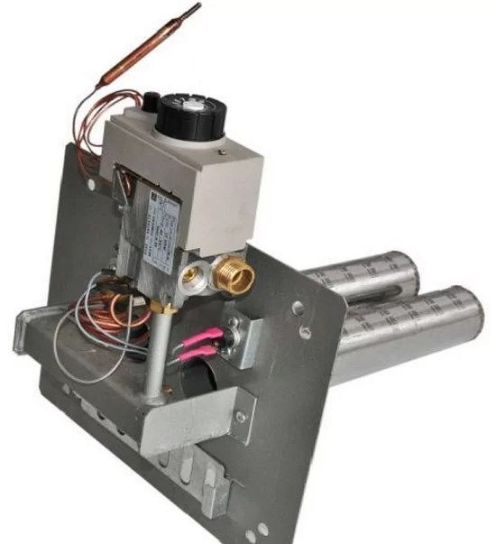
The newest models of gas boilers are characterized by high power and heating speed. However, the prices for them, to put it mildly, bite. You can try to use more economical option and put new automation on the old boiler or fix the old one. The principle of operation and the device of automation of old-style gas heating boilers will be explained in this article.
The old-style boilers were manufactured in accordance with the gas parameters and the characteristics of the heating system, which were in use several decades ago. These are, for example, the KChM and AOGV models. Moreover, their strength makes it possible to operate them for many years to come. But the trouble with automatics, quite often it breaks down. In such a situation, there are three options:
- diagnose existing automation and replace the necessary parts;
- equip a reliable and high-quality unit with a modern automatic system;
- purchase a new boiler.
The difference, of course, is in the price of the issue, the efforts and time of the owner.
Consider the cheapest option - troubleshooting gas automation to the old boiler. However, first, let's figure out what it is generally provided for. automatic system in the coolant.
Gas automation allows you to regulate and maintain the required temperature level of the coolant, and also serves to automatically stop the gas supply in an emergency situation. Installing automation on an old gas boiler will make sure that if the burner flame goes out, then after a short time the system will work to stop the gas supply without your participation. 
Attention!
Automation, in addition to regulating and maintaining the temperature at a given level, ensures the safety of use heater and allows you to save on heat consumption.
If you want to change the automation, then keep in mind that domestic manufacturers produce models that are suitable for almost any old coolant. Imported automation can not be installed on everything. In addition, when installing foreign automation on old-style gas boilers, not all of its functions may work - they will not allow design features boiler.
On a note!The choice of automation for gas boilers is varied. The most popular is the system from Italian manufacturers e.g. SIT. The second most popular is American automation (Honeywell). There is a great choice of Russian (SABK, Orion) and Ukrainian manufacturers (Fakel, Iskra, Flame, APOK-1).
The principle of operation of automation on old-style gas boilers
Frequent problems when heating a room gas boilers the attenuation of the flame in the burner and the gas content of the room are. This happens for several reasons:
- insufficient chimney draft;
- too high or too low pressure in the pipeline through which the gas is supplied;
- the extinction of the flame on the igniter;
- leaks in the impulse system.
When these situations arise, the automation is triggered to stop the gas supply and does not allow the room to be gassed. Therefore, the installation of high-quality automation on an old gas boiler is an elementary safety rule when using it to heat a room and heat water.
All automation of any brand and any manufacturer has one principle of operation and basic elements. Only their designs will differ. Old automatics "Plamya", "Arbat", SABK, AGUK and others work according to the following principle. In the event that the coolant cools below the temperature set by the user, the gas supply sensor is triggered. The burner starts heating the water. After reaching the temperature set by the user on the sensor, the gas sensor is automatically turned off.
On a note!When using modern automation, it is possible to save heat up to 30%.
The old-style automation is non-volatile and does not need electricity. Its adjustment, connection and disconnection are made by a person. Commands are transmitted using electromagnetic pulses.
The video tells how the automatic equipment of gas boilers AOGV, KSTG works.
Basic elements of automation
The main elements of automation for a gas boiler are:
- thermostat;
- shut-off valve;
- thrust sensor;
- flame sensor;
- igniter tube;
- igniter;
- burners.
Let's try to explain in an accessible way how the automation for a gas boiler works, disassembling it into basic elements and telling about their functions.
The gas passes through the gas cleaning filter. Then it goes to the solenoid valve that regulates the fuel supply to the burner. Temperature and draft sensors are located next to the valve, which monitor the indicators and signal that they are outside the permissible limits. Also, the set of automatics for gas boilers includes a thermostat with a bellows and a stem, designed to set the desired temperature. A special button is used to adjust the indicators. When the water heats up to the temperature set by the user, the thermostat is triggered, the gas supply to the burner stops, while the igniter continues to work. When the water cools down by 10-15 degrees, the gas supply is resumed. The burner ignites from the pilot. Automation is started manually. 
Flame and draft detectors
Flame and draft detectors work according to this principle. The draft sensor reacts to the deterioration of the smoke draft and transmits an impulse to the control system. It is located in a smoke hood. Equipped with an alloy plate of two metals: iron and nickel. When draft deteriorates, flue gases accumulate and heat up the plate. It is deformed, the contacts open at the same time, the flow of fuel into the combustion chamber stops. When the temperature decreases, the plate returns to its normal state.
The temperature sensor works the same way. When the water in the boiler is heated above the set temperature, the lever mechanism is triggered and the temperature regulator valve closes. The gas flow stops and the burners go out.
When the water cools down, the sensor bellows contracts, the lever mechanism is triggered, the temperature regulator valve opens, gas begins to flow, and the burners light up.
The most frequent malfunctions of automation and methods of their elimination
Before setting up the automation on the boiler, it is necessary to diagnose it. As a rule, serious malfunctions occur that require specialist intervention. The adjustment can also be entrusted to the gas master. Or you can make it yourself by reading the instruction manual.
Attention!Before each seasonal operation, the safety sensors must be checked for proper operation.
Most often, the filter becomes clogged, problems arise with the valves, due to voltage surges, sensors burn out, and a gas leak is detected. The correct cleaning of the filter must be done by a master. You can try to replace electronic elements yourself, having carefully studied the operating instructions for your boiler. 
In order to replace the temperature sensor, it is necessary to turn off the gas boiler and cool the water to a temperature of 40 degrees. Shut off the coolant flow, remove the control knob by unscrewing the screw. Next, dismantle the PTV adjustment screw. Remove sensor bellows with support washer. Unscrew the union nut of the sensor bulb. Install the thermal bulb of the serviceable sensor into the boiler jacket and screw it tight. Install the sensor bellows into the pipe socket, install the support washer on the bellows, install the PTB adjustment screw and adjust the temperature.
If there are problems with igniting the igniter, then one of its possible causes is a malfunction of the draft sensor. In this case, it is necessary to dismantle it, diagnose it, check the contacts, clean it, and, if necessary, replace it with a new one.
Also common reasons why the igniter does not light up, there may be:
- malfunction of the gas valve;
- clogging of the hole in the igniter nozzle (it is possible to clean it with a wire);
- strong air draft;
- low gas inlet pressure.
When the gas supply is turned off, it is necessary to check the chimney (it may be clogged), the electromagnet, the gas pressure at the inlet to the gas boiler. 
It is necessary to invite a specialist to diagnose and repair the automation of a gas boiler. Inappropriate actions can exacerbate the problem and have undesirable consequences.
For automation systems AGUK, AGU-T-M, AGU-P, the most common problem is the burnout of the bimetallic plate, which is used as a sensitive element.
In "Arbat" and "Orion" only the thermocouple and the thrust sensor, as well as the solenoid valve (rarely) can be replaced. The automation unit is practically beyond repair. In Arbat, the system shutdown button often breaks.
Typical problems for SABK automation are damage to the main valve membranes, drying out of the stuffing box of the thermostat, resulting in a gas leak. Impulse tubes, bimetallic plates, ball valves are subject to control.
In conclusion, I would like to emphasize once again that automation is designed to maintain operation heating equipment in safe mode. Therefore, it is simply necessary for the owners of gas boilers.
This video shows the elimination of a malfunction of the AOGV boiler automation, step by step process assembly and testing of the result.
Description and purpose of the main elements. The principle of operation of the device and the diagram of the gas cylinder installation.
Essential elements
Reducer-evaporator. A system element designed for heating the propane-butane mixture. It controls evaporation, reduces pressure to atmospheric. Structurally, a gas reducer is a mechanism consisting of several chambers connected in series. They are separated from each other by valves.
Electromagnetic valve for gas. The mechanism is designed to block the fuel line. This is necessary when the engine is idle, after switching to motor gasoline. The valve is additionally equipped with a fuel filter.
Electromagnetic valve for gasoline. This mechanism stops the supply of gasoline to carburetor engines when they are running on a gas mixture. The gas control unit performs a similar task in injectors.
Vehicle fuel switch. This mechanism is equipped in the salon. vehicle... Switches may differ in design. Some options have a backlight, an indicator scale that shows how much gas mixture is left in the cylinder.
Multivalve. The mechanism is located on the neck of the cylinder. Its design includes the following valves: high-speed, consumable, filling. Additionally, the multivalve is equipped with an intake pipe and a fuel mixture level meter. A high-speed valve in case of a pipeline breakdown prevents gas leakage.
Ventilation chamber. This system component is also located on the neck of the bottle. A multivalve is placed in the box. The main function of this element is to evacuate gas vapors outside when a gas leak occurs in the trunk.
Gas cylinder (special container for keeping liquefied gas). It can be toroidal or cylindrical. The first option provides the ability to place a container with gas in a niche designed to store a spare wheel. According to safety regulations, when operating gas cylinders, the container is filled with a gas mixture to only 80% of its maximum capacity.
Analysis of the details of the fourth generation LPG equipment set: what the details of the device look like, why they are needed and how everything works
Principle of operation
It should be noted that feeding with a gas mixture, the execution of the entire gas cylinder system of previous generations is much simpler than the design of a gasoline system for supplying a fuel mixture.
Transfer of a vehicle to work on gas equipment, its corresponding conversion looks like this. Previously, in the luggage, cargo compartment, under the bottom of the car, on the frame, a special container is mounted, designed for filling with gas. In the engine compartment (engine compartment), a reducer-evaporator, additional devices, the functions of which are associated with the supply of a gas mixture to the engine, and fuel adjustment mechanisms are installed.
The cylinders are filled with a liquid propane-butane mixture. If the pressure is at atmospheric pressure, the fuel is in a gaseous state. If the pressure is higher than atmospheric pressure, the gas is converted into liquid fuel, which can evaporate at domestic temperatures. Therefore, only sealed containers are used for liquefied gas. The pressure in them can be 2-16 atmospheres.
Gas vapors form pressure, due to which they are supplied to the high-pressure gas pipeline. The filling of the gas cylinder and the supply of fuel from it to the line is carried out through the multivalve. To carry out refueling, a special external device is additionally used.
The liquefied gas mixture is directed through a pipeline and passes through a gas valve with a filter element. Such additional filtration makes it possible to more effectively purify the fuel from resinous compounds and other impurities. This device is also designed to block the supply of the gas mixture when the ignition is turned off, the engine operating mode is switched to gasoline.
After filtration, the fuel mixture is sent to the gearbox. Here, the pressure of the gas mixture drops to about 1 atmosphere. The decrease in pressure facilitates the evaporation of the liquid gas mixture. During this process, the gearbox is actively cooled. It is for this reason that it is connected to the cooling system of an automobile engine. The heated coolant, as a result of circulation through the system, does not allow the gearbox to freeze up. In the cold period of the year, it is recommended to start with gasoline, and after preliminary warming up of the engine, it is worth transferring its operating mode to gas equipment. This requirement assumes the output of the motor to the working temperature regime, as well as heating the coolant to the required temperature.
After the reducer, already the vaporous gas is directed into the cylinders of the motor. There is no part in the GB system that is functionally similar to a gas pump. The gas mixture is contained in the cylinder under a certain pressure, and enters the reducer autonomously; additional pumping is not required for this. Thanks to this, the HBO system is much simpler in design. And the ability of a gas to transform from liquid to vapor when the temperature and pressure change, further reduces the number of structural elements of LPG installations.
A special switch installed in the car interior allows you to switch from petrol to gas and vice versa. After turning off the ignition, the switch is in neutral. Gas equipment can be additionally endowed with the function of turning off the gas mixture supply if there is no spark in the car engine.
Installation diagram
- Gas container (cylinder)
- Multivalve
- High pressure fuel line
- Refueling outrigger
- Gas valve
- Reducer-evaporator
- Fuel mixture dispenser
- Gasoline valve
- Fuel switch

According to the GB fuel supply scheme, the equipment is conditionally subdivided into generations. For example, consider early systems, analyze their working algorithm. The propane-butane mixture in a liquefied state, contained under a certain pressure in a specialized container, is fed into the high-pressure pipeline through a special multivalve that fixes the fuel consumption. Refueling is carried out using this valve and a remote filler. Further, the liquefied gas passes through the pipeline through a gas valve, additionally equipped with a filter element, where it is purified from various impurities, resinous compounds. This mechanism of the system, with the ignition off, switching the engine operating mode to gasoline, cuts off the gas mixture supply.
Then, through the pipeline, the clean gas moves to the reducer, where its pressure is reduced to atmospheric. As a result of this procedure, the gas mixture begins to evaporate intensively. A vacuum is formed in the collector of a running motor, which makes it possible for the gas mixture to pass through the reduced pressure hose. Then the gas is directed through the metering device to the fuel mixer, which is located between the throttle and the air filter. A gas connection can be used on carburetor engines.
The required type of fuel for the engine operation is switched on by the fuel switch located on the panel from the passenger compartment. When the "gas" mode is turned on, the switch activates the opening of the gas valve, at the same time the petrol valve is closed. When switching the operating mode of the car engine to petrol, the gas valve is closed accordingly. Thanks to the illumination provided for the switch, you can always see what fuel the engine is running on.
Many car enthusiasts, especially in the face of constantly rising fuel prices, decide to switch their car from petrol to gas. Installation of gas equipment allows you to significantly save money for those drivers who actively operate their car and have solid mileage. We will talk about the advantages and disadvantages of using HBO in a separate article, but now let's look at the classification of such solutions and the principle of operation of such equipment.
Read in this article
Gas system device
Main components of gas systems:
- Reducer-evaporator. This device realizes the heating of the propane-butane mixture, is responsible for evaporation and reduces the pressure to a value close to atmospheric. The gas reducer is perfect for cars with a small working volume, since this compact solution is not difficult to place in the engine compartment. The device can be controlled both vacuum and electronic using a separate unit.
- Electromagnetic gas valve. It closes the gas line, which is necessary during idle time or after switching the engine to gasoline. It also has a filter that cleans the fuel mixture.
- Electromagnetic petrol valve. In cars with the carburetor stops the gas supply when the engine is running on gas. In a car with injection injection, this function is performed by injector emulator.
- Fuel switch. The device is located in the passenger compartment of the vehicle. The switches can be of various designs, some of them are backlit and have a scale indicating the remainder of the gas in the cylinder.
- Multivalve. This solution is mounted on the neck of the cylinder. The device consists of a filling valve and a flow valve. There is also a gas level meter and an intake pipe. Structurally, the device includes another valve (high-speed), which is able to prevent gas leakage in the event of an emergency breakdown of the gas line.
- Ventilation box. The solution is also installed on the neck of the bottle. The multivalve named above is placed inside the box. The main task of the ventilation box is to evacuate gas vapors to the outside in the event of gas leaks from the cylinder in the luggage compartment.
- Capacity for liquefied gas (gas cylinder). The cylinders can be cylindrical and toroidal. The latter allow for installation in the spare wheel well. The cylinders are filled to no more than 80% of the maximum volume, which is done in accordance with safety requirements during their operation.
Principle of operation
It should be noted that the gas supply and the implementation of the entire LPG system of early generations are noticeably simpler than the device of a gasoline fuel supply system. For clarity, let us once again draw your attention to a relatively small list of basic elements.
The conversion of the car to the gas supply system and the corresponding conversion is as follows. At the very beginning, a container for storing gas (gas cylinder) is installed in the trunk, cargo compartment, on the frame or under the bottom of the vehicle. The engine compartment houses a reducer-evaporator and devices responsible for supplying gas to the engine. Additionally, solutions are installed that allow for the regulation of the mixture.
The gas in the cylinder is propane-butane, which is liquefied petroleum gas. If the pressure is at the atmospheric level, then the substance is in a gaseous state, but with a relatively small increase in pressure, it easily turns into a liquefied state. The resulting liquid tends to evaporate at household temperatures. For this reason, the gas is placed in sealed containers (cylinders) under a pressure of 2-16 atm, where it is stored as a liquid.
Gas vapors create pressure, so that from the cylinder they enter the gas line, which is called the high-pressure line. Gas is consumed from the cylinder due to its passage through the multivalve. As mentioned above, gas filling is also carried out through this valve. An additional external device is used for refueling.
Gas in a liquid state moves along the line and enters the gas valve equipped with a filter. The filter is designed for effective gas cleaning from impurities and tarry deposits. The device is additionally responsible for shutting off the gas supply at the moment the ignition is turned off, as well as when the engine is running on gasoline.
After the filter, the purified liquefied gas moves through the gas pipeline and ends up in the reducer-evaporator. In this device, its pressure is reduced to approximately equal to 1 atm. A decrease in pressure leads to the fact that the liquid gas begins to evaporate. In this case, the gearbox is actively cooled. For this reason, the gearbox is connected to the motor cooling system. The heated coolant that circulates in the system prevents the gearbox and diaphragms from freezing up in the device. The main recommendation in the cold season is to first start and warm up the engine on gasoline, and then the engine is switched to gas. This requirement implies that the internal combustion engine reaches operating temperature with the necessary heating of the coolant.
From the reducer, the gas, which is already in a vaporous state, enters the engine cylinders. Dosing devices are responsible for its supply. It is noteworthy that the device gas installation there is no element that is similar in function to a gasoline pump. The gas is already in the cylinder under pressure and enters the reducer on its own, and not forcibly. This greatly simplifies the LPG system. The ability of a gas to change from a liquid to a vapor phase when changing pressure and temperature further reduces the number of structural elements in the circuit.
The mixer in the LPG is a complex-shaped device that is installed in front of the throttle valve. The main task of this solution is to prepare a working mixture of gas and air. The dispenser is an adjustment device. A special solenoid valve is installed in front of the reducer, which cuts off the gas supply.
The switch for selecting petrol or gas in the passenger compartment has three positions: "gas", "petrol" and neutral position. The mode selection closes one or both valves. When the ignition is turned off, then all the valves are closed. LPG equipment can also have the function of turning off the gas supply in the event that there is no ignition spark in the internal combustion engine.
- balloon (1)
- multivalve (2)
- high pressure gas line (3)
- remote filling device (4)
- gas valve (5)
- reducer-evaporator (6)
- dispenser (7)
- air and gas mixer (8)
- the petrol valve (9)
- fuel switch (10)
According to the principle of gas supply to the engine, LPG is conventionally divided into generations. As an illustrative example, let's take early systems and follow the algorithm of their work. Petroleum gas (propane-butane), which is in a liquefied state and under pressure, comes from a cylinder (1). Gas flows through the high pressure line (3). The multivalve (2) is responsible for gas flow control. Through the same valve, filling is carried out using an external filling device (4). In the liquid phase, the gas enters the gas filter valve (5) through the pipeline. There it is cleaned of suspended solids and tarry deposits, and the filter cuts off the gas supply when the ignition is turned off or when the operating mode is on gasoline.
The gas purified in the filter goes through the pipeline and ends up in the reducer-evaporator (6). The gas pressure drops there to the atmospheric level. Intense gas evaporation begins. The vacuum in the intake manifold of a running internal combustion engine allows the gas from the reducer to pass through the low pressure hose. Then the gas enters the dispenser (7) and ends up in the mixer (8). The mixer is installed between the air filter and the throttle valve. On carburetor cars, instead of a mixer, gas fittings can be inserted directly into the carburetor.
The operating modes of the internal combustion engine on petrol or gas are selected using the fuel type switch (10), which is placed on the dashboard. When the gas mode is selected, the switch initiates the opening of the gas solenoid valve (5) and the petrol solenoid valve (9) is deactivated. If there is a transition from gas to petrol, then the switch closes the gas valve and allows the petrol valve to open. The backlight on the switch allows you to determine which type of fuel is being used at any given moment.
In the course of evolution, a well-established practice of dividing attitudes into generations has developed. In the CIS, certain difficulties arose with the classification of LPG. The fact is that the third generation, after its appearance on the market, did not become widespread and then disappeared, and the first and second for this reason were mistakenly called the second and third.
Even more confusion is caused by numerous installers, who in some cases erroneously assign the status of the fifth generation to LPG systems with OBD correction, as well as BRC Sequent Direct Injection systems for engines with direct fuel injection. For maximum clarity, the system should be divided according to the method of gas supply to the internal combustion engine:
- ejector-type equipment, which includes the first generation HBO. The solution is analogous to the gasoline carburetor and early models of injection injection;
- distributed gas injection, belonging to the fourth generation of systems;
- liquid injection, which is the fifth generation of HBO;
- direct injection of liquid gas, which is the sixth generation of gas equipment;
HBO generations and design features
1st generation
This generation includes mechanical systems that have been partially described above by way of a schematic example. The solutions are vacuum controlled and equipped with a mechanical gas meter. Such systems are installed on gasoline units that structurally have a carburetor or a simple injector. The first generation HBO also received a gas mixer.
The regulation of the gas supply to the mixer for such systems is carried out manually. For this, a dispenser is used. The dispenser is a branch pipe that allows you to change the flow area by screwing in an adjusting screw that is inserted into the branch pipe. By adjusting the dispenser, we mean such a position of the screw that allows the motor to operate stably on gas in various modes. The position of the screw during the operation of the car may occasionally require correction, especially when the air filter is clogged. The fuel selection switch in such LPG equipment may additionally have a gas level indicator in the cylinder. The function is realized if there is a fuel level sensor in the multivalve design.
The first generation of LPG for cars with an injector is structurally different in that the petrol valve for stopping the supply of petrol is replaced by a device called an injector emulator. In the process of gas supply, the element simulates the operation of regular gasoline injectors so that it does not go into emergency operation. A similar solution in the form of a lambda probe emulator made it possible to solve the problem regarding errors in the injection engine ECU.
2nd generation
The mechanical system was supplemented by an electronic metering device, the operation of which was based on feedback from a lambda probe (oxygen content sensor). This solution is installed on injection engines with a catalyst. HBO of the second generation got rid of the manual dispenser. Its place was taken by an electronic dispenser, which regulates the gas supply using a stepping-type electric motor.
The dispenser is controlled by an electronic unit, which relies on the signals of the standard lambda probe. This allows maintaining the optimal composition of the gas-air working mixture. The electronic unit additionally receives signals from the throttle position sensor and the engine speed sensor, which is necessary to optimize the mixture during transient operating modes of the power unit. This type of HBO is configured using a PC.
Such systems were installed on cars with electronic carburetors or injectors, which are equipped with a lambda probe and a catalyst, and have a throttle position sensor in the design. These generations of LPG are transitional systems. Today, such solutions are practically not used.
The reason was that the early generations of HBO do not meet the current requirements on the issue of toxicity, being at the level of EURO-1 standards. With these requirements in mind, manufacturers have created systems of the third and fourth generations, which are much more common.
3rd generation
Such systems are capable of providing distributed synchronous gas injection. Structurally, they have a dispenser-distributor controlled by an electronic unit. The gas supply to the intake manifold is realized by means of mechanical injectors. The injectors are opened by excess pressure in the high-pressure gas line. An electronic-mechanical stepping-type metering-distributor is located between the reducer, which supplies excess pressure, and the valve connections, which are installed in the engine intake manifold. The element is responsible for the optimal dosage of the gas flow into the inlet. Switching modes and creating an optimal gas-air working mixture is entrusted to the electronic control unit, which receives signals from the standard engine sensors (MAP sensor, lambda probe, DPDZ, etc.).
It is worth noting that the 3rd generation HBO does not use the car's ECU and does not rely on fuel cards that are wired into the standard ICE control unit. Gas supply systems operate in parallel and have their own fuel cards. Correction of the composition of the mixture in such HBO is not of the highest quality, which directly depends on the speed of the step-by-step dispenser-distributor. After the introduction of the EURO-3 standards, as well as the emergence of OBD II and EOBD systems (on-board diagnostics of the second generation), gas systems of the 3rd generation have lost their popularity. The release of the 4th generation LPG systems completely displaced the previous 3rd generation from the market.
IV generation
HBO of this generation is called distributed gas injection (the definition of phased distributed gas injection is also found). The generation of distributed sequential gas injection systems with electromagnetic injectors is controlled by a more advanced electronic unit. Like the 3rd generation systems, the gas injectors are mounted on the intake manifold. Installation involves the close proximity of the injector nozzle and the intake valve of each individual cylinder. This generation of LPG uses the power of the ECU and, which are included in the standard program of the car controller. In the 4th generation, only the necessary adjustments are made in order to adapt the gas system to the fuel map in the petrol ECU.
In this generation of systems, the gas from the reducer-evaporator passes through a fine gas filter. Then it enters a special gas injector rail. These injectors are installed on the intake manifold, and the space near the regular gasoline injectors becomes their place of installation. The gas injectors are based on calibrated jets, through which gas is supplied to the area where the inlet valve of the power unit is located.
A separate control unit controls the gas injectors. The unit uses the signals that come from the standard on-board computer in the car and are intended for petrol injectors. The gas block converts these signals and sends them to the gas injectors. The petrol injectors are switched off at this moment by the same block.
The required amount of gas, which is distributed over the intake manifold, is calculated based on the injection time, which is determined by the standard ECU. The gas injector control unit adjusts this time for the gas, since its pressure and temperature must be taken into account. The result is that gas enters each cylinder of the internal combustion engine in a timely manner and in a precisely defined amount.
HBO 4th generation is configured using personal computer and related programs. The software must be compatible with the HBO generation. A separate advantage of such systems is the function of switching from petrol to gas in automatic mode when the engine is warming up. If the gas in the cylinder runs out, then an automatic switch to petrol will also occur. The ability to manually select fuel using a switch in the cabin remains unchanged. Today HBO of the 4th generation is the most popular and optimal equipment for injection vehicles.
HBO IV and direct injection
Separately, it is worth noting the 4th generation HBO for such cars in which the fuel supply system is arranged according to the principle of direct fuel injection. Some LPG installation companies attribute this type of system to the fifth generation, but a detailed study of the issue reveals the erroneousness of this definition. In fact, the system remains 4th generation equipment, which has been modified and adapted for a specific type of internal combustion engine.
Not so long ago, the installation of LPG on cars with direct fuel injection into the cylinders was simply impossible. These cars include Mitsubishi with a line of GDI engines, VW, Skoda and Audi with FSI units, some Toyotа, Nissan models, etc. The main problem was that gasoline injectors in such engines do not inject fuel into the intake manifold, but supply fuel directly to the combustion chamber. It was not possible to install gas injectors for direct gas supply to the combustion chamber. The usual HBO of the 4th generation with gas nozzles on the intake manifold was also not suitable, since the gasoline power supply system of these internal combustion engines suffered greatly and failed in a short time.
The LPi (Liquid Propane Injection) system is a liquid gas injection. This system was the brainchild of the Dutch company Vialle. The brand's specialists developed and were the first to present the gas injection system, which is in a liquid state, back in 1995. The main difference of this system from other LPG systems with distributed injection is that the gas is injected into the intake manifold of the internal combustion engine not in the vaporized phase, but in liquid form. This generation gas system it also has a number of differences in its component components. Most of the elements of the LPi system differ from those familiar solutions that are used in the design of the usual previous LPG systems.
There is a gas pump in the gas cylinder. The specified pump makes it possible to provide gas supply in a liquid state. As such, the gas flows to the gas injectors. The need to evaporate the gas in the intake manifold has disappeared, which automatically eliminates the reducer-evaporator from the system. Instead of this element, there is a pressure regulator. The task of the device is to maintain a constant operating pressure in the gas supply system. The reading is at such a mark that the outlet pressure is at least 5 bar higher than the pressure in the gas cylinder. This pressure does not allow the gas to go into the vapor phase in the tubes due to the heating of the running engine. The need to preheat the LPG elements under the hood by integrating them into the internal combustion engine cooling system to circulate the heated coolant has now lost its relevance. The pressure regulator is enclosed in a special block, which contains a safety solenoid valve. This valve is open when the internal combustion engine is running on gas, the device is closed when the engine is switched to gasoline.
Remains of unused gas from the injectors go through the pressure regulator back to the cylinder, which resembles the principle of "return" in gasoline units. The fuel line has also changed. In the early generations of HBO, there was a tube, the material of which, in most cases, was refined copper. The tube was used to supply gas from a cylinder to a reducer-evaporator. In the 5th generation system, it was replaced by single lines, the material for which was reinforced plastic.
If you carefully examine the LPi system, then it is quite obvious that there is a significant similarity with the gasoline fuel injection system for the internal combustion engine. Liquid injection allows you to completely replace the gasoline power system. South Korean automakers have appreciated this opportunity by launching mono-fuel gas vehicles for their domestic market.
The main advantage of HBO 5 is its high injection accuracy, lack of connection to the internal combustion engine cooling system, independence from the level of gas pressure in the cylinder, etc. Moreover, due to the cooling effect during gas evaporation, the motor, when operating in some modes, produces a slightly higher power.
It becomes easier to start an internal combustion engine in low temperatures, since in cold weather in LPi liquefied gas has better performance vaporization in comparison with gasoline, which allows you not to fill candles. The disadvantages of the system include the high final cost and little experience in servicing these solutions by specialists in the territory of the CIS countries.
If the system is not properly maintained, then the life of the 5th generation HBO without breakdowns is reduced significantly. For example, an old-style gas pump required periodic lubrication to run smoothly. Not all specialists knew about this need. Hence, myths arose about the rapid failure of gas pumps, which were attributed to the low quality of gas in the CIS, design flaws in the system, etc.
Correct maintenance, even taking into account the realities and mediocre gas quality, is able to ensure the minimum resource of Vialle LPi, even with an old-type pump of about 200-300 thousand km. V modern systems an even more advanced turbine-type pump was used, which completely eliminates the need for additional lubrication and other manipulations to maintain the system.
VI generation
Liquid Propane Direct Injection is a solution for direct injection of liquid gas. In parallel with the LPi system, the Dutch company Vialle created the LPdi system. This solution is intended for engines with direct injection of fuel into the cylinders.
This system occupies the conditional status of the sixth generation of HBO, repeating the situation with the 4th generation and the Sequent Direct Injection (SDI) system. The solution has a similar design to the 5th generation LPG. The main difference is that liquid gas is supplied through the standard gasoline injectors of the power unit. The system uses the same bottle with a high-pressure gas pump. This pump supplies LPG to a special device called a fuel selector. It is in this device that the switching between the supply of petrol or gas takes place.
It is quite obvious that the specified fuel selector acts as the basis of this LPG system. This device is a patented valve block. During the operation of the unit, gasoline in front of the high-pressure fuel pump is replaced with liquid gas. Remaining in a liquefied state, the gas is supplied to. Specified
raises the pressure up to 100 bar and more, supplying gas to the fuel injectors-injectors.
The use of such an LPG system allows you to fully preserve all the advantages of using an internal combustion engine with direct fuel injection. The most accurate dosing of fuel is ensured, the engine operates confidently on a lean working mixture, there are no problems in transient modes. Moreover, the use of liquefied gas can further reduce the toxicity of the exhaust.
Another positive point from the use of the 6th generation HBO is the ability not only to maintain the engine power that the engineers put into it at the plant, but also to exceed this figure. The manufacturer gives an example that after the installation of such an LPG system on the Volkswagen Passat 1.8 TSI, the rated power of which on gasoline is 160 hp, the power characteristic on gas increased to 169 hp. With. It is possible to install the Vialle LPdi system only on certain car models with the corresponding type of power unit.